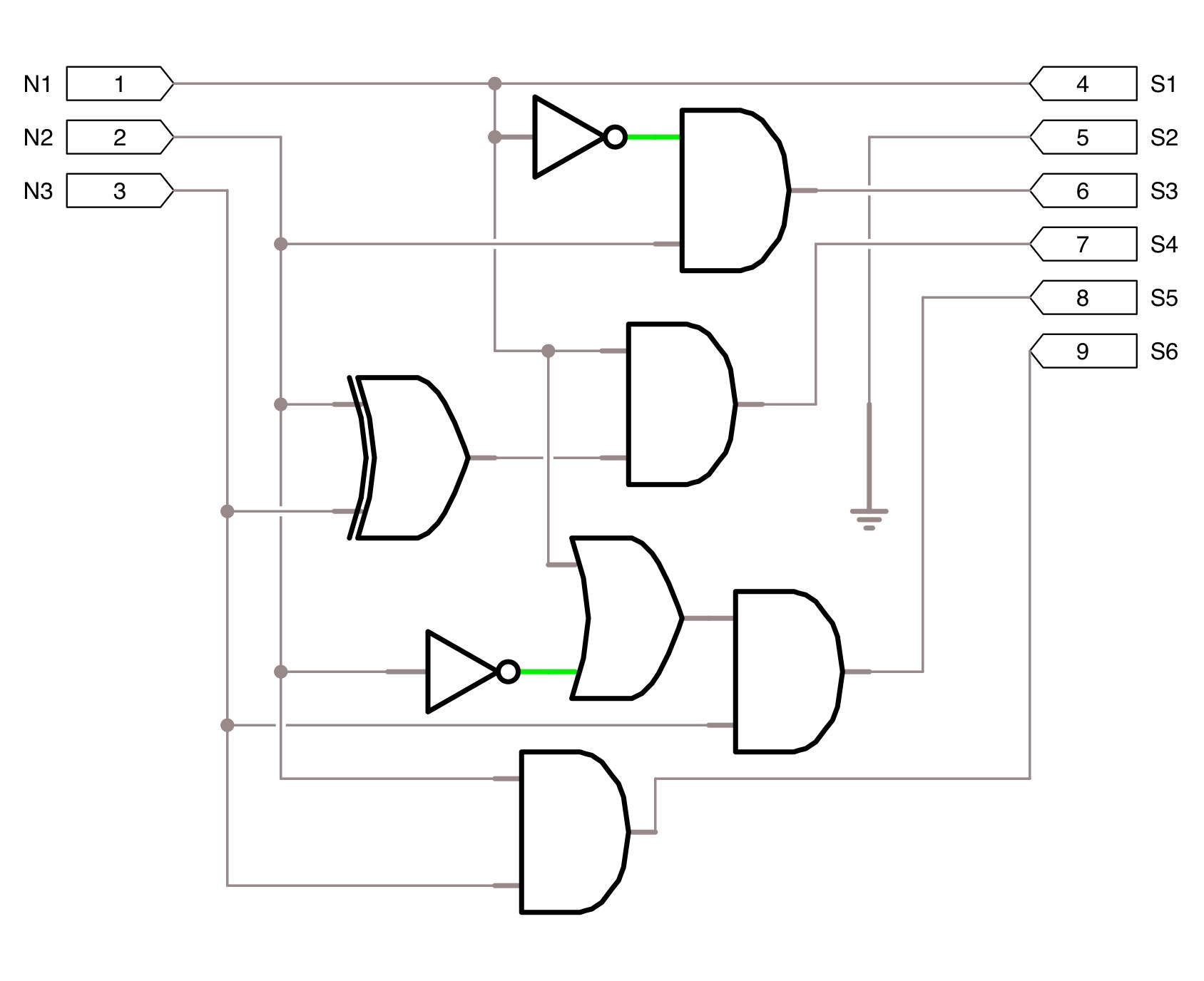
[Solved] Please show work. Part 3: Circuit Implementation (50 points

3 Input And Circuit Diagram

Bit logic gates using binary input square two adders make even squarer questions stack Input plc signal programming separated

Understanding circuit diagrams Transcription circuit Ldr circuit diagram

All About PLC Analog Input and Output Programming

All about plc analog input and output programming

Square 3 bit input using two 3 bit adders and logic gates

Ttl nand input gates circuit diagram gate logic states digitalConnecting to an external device, connection, wiring [solved] please show work. part 3: circuit implementation (50 pointsTtl nand and and gates.

Ldr circuits dependent resistorsCircuit diagram simple components physics explanation symbols its Keyence rs1a wiring connecting.
square 3 bit input using two 3 bit adders and logic gates - Electrical

LDR Circuit Diagram - Build Electronic Circuits

Connecting to an external device, Connection, Wiring | KEYENCE DL-RS1A

[Solved] Please show work. Part 3: Circuit Implementation (50 points
[Solved] Please show work. Part 3: Circuit Implementation (50 points

Understanding Circuit Diagrams - Components, Reading Guide and Examples

All About PLC Analog Input and Output Programming

TTL NAND and AND gates | Logic Gates | Electronics Textbook